The hybrid digital stepper driver is controlled by the latest 32-bit ARM processor. This digital driver has peripheral subdivision, current, and auxiliary function dialing, which users can freely set according to their needs. Advanced drive control algorithms are written internally to ensure precise and stable operation of the stepper motor in various speed ranges. The built-in subdivision algorithm enables the motor to run smoothly at low speeds; The medium to high speed torque compensation algorithm can maximize the torque of the motor at medium to high speeds; Parameter self-tuning algorithm, capable of adapting to various motors and maximizing motor performance; Built in smoothing algorithm can greatly improve the acceleration and deceleration performance of the motor.
1. Productfeature
2. Electrical indicators
Instructions | DM422 | |||
minimum | typical value | maximum | unit | |
output current | zero point three | - | two point two | A |
Input power supply voltage | twenty | twenty-four | forty | VDC |
Control signal input current | seven | ten | sixteen | mA |
Step pulse frequency | 0 | - | two hundred | KHz |
insulation resistance | fifty |
|
| MΩ |
three Usage environment and parameters
cooling method | Natural cooling, fan cooling | |
Usage environment | occasion | Cannot be placed next to other heat generating equipment. Avoid dust, oil mist, corrosive gases, high humidity, and strong vibration areas. Combustible gases and conductive dust are prohibited |
temperature | 0——fifty℃ | |
humidity | forty—90%RH | |
vibration | 10~55Hz/0.15mm | |
storage temperature | -20℃~65℃ | |
status indicator
greenLEDFor the power indicator light, when the driver is powered on, theLEDAlways on; When the drive is powered off, theLEDExtinguish.
redLEDAs a fault indicator light, when a fault occurs, this indicator light willthreeFlashing in cycles of seconds; When the fault is eliminated by the user, redLEDConstant extinction. redLEDatthreeThe number of flashes per second represents different fault information, and the specific relationship is shown in the following table:
serial number | Number of flashes | redLEDFlashing waveform | Fault Description |
one | two |
| Overvoltage fault (voltage)>DC40V) |
two | three |
| Undervoltage fault (voltage)<DC20V) |
three | five |
| Motor open circuit (phase loss) |
Common problems and troubleshooting
1. Interface Description
1)Control signal interface
2)Strong power interface
name | Function |
AC2 | Universal AC and DC, regardless of positive or negative, range AC18~55V/DC20~80V |
AC1 | |
A+、A- | Motor A phase coil |
B+, B- | Motor B phase coil |
GRMOT Stepper Motor and Driver Model Matching Table:

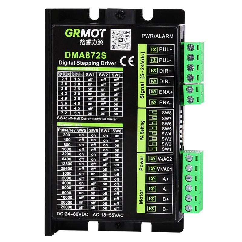
The DMA872S driver uses an 8-bit dip switch, SW1-SW3 is used to set the current; SW4 selects full current or half current lock; SW5-SW8 is used for subdivision settings. The detailed description is as follows:
SW1 | SW2 | SW3 | SW4 | SW5 | SW6 | SW7 | SW8 |
Current setting | Semi-stream | Segment settings | |||||
1. Current setting
Output peak current(A) | Output effective current (A) | SW1 | SW2 | SW3 |
2.1 | 1.5 | off | off | off |
2.8 | 2.0 | on | off | off |
3.5 | 2.5 | off | on | off |
4.2 | 3.0 | on | on | off |
4.9 | 3.5 | off | off | on |
5.6 | 4.0 | on | off | on |
6.4 | 4.5 | off | on | on |
7.2 | 5.1 | on | on | on |
2. Quiescent current setting
The static current can be set with the SW4 DIP switch. Off means the static current is set to half of the dynamic current, and on means the static current is the same as the dynamic current. In general use, SW4 should be set to off to reduce the heat of the motor and driver and improve reliability. After the pulse input stops, the current is automatically reduced to half.
 Company Profile