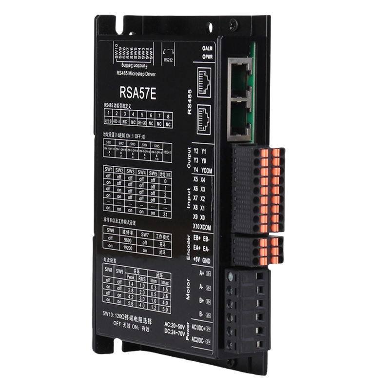
four hundred and eighty-fiveBus type openingcloseringstepThe driver ismostNewly launchedEquipped with serial port debugging functiondigitalmixstepservoDriver,integratedMODBUS-RTUStandard protocol specifications,Communication network portadoptstandardRJ45Interface, userSoftware can be debugged through the upper computerSet segmentationVarious parameters such as current, speed, working mode, etc,Greatly enriching the practical functions of the product,canenoughMeet the application needs of most occasions.
four hundred and eighty-fiveBus type openingcloseringstepdriveAdopting the control principle of class servo,Compatible with the dual advantages of open-loop stepper and servo systems,Adopting the latest technologythirty-twobitDSPcontrolTechnology,Greatly improved the performance of the stepper system.Medium low speedallHas excellent stability and ultra-low noise,High speed torquealsoGreatly improved, expanding the speed application range of stepper motors.Smooth and precise pure sine current vector control technology effectively reduces motor heatingAnd it has strong compatibility and high cost-effectiveness, which can meet the needs of the vast majority of applications.
Instructions | four hundred and eighty-fiveBus type open-loop and closed-loop driver | |||
minimum | typical value | maximum | unit | |
output current | 0 | - | six thousand | mA |
Input power supply voltage | twenty | - | fifty | VAC |
twenty-four | thirty-six | seventy | VDC | |
Control signal input current | seven | ten | sixteen | mA |
insulation resistance | fifty | - | - | MΩ |
cooling method | natural coolingFan cooling | |
Usage environment | occasion | Cannot be placed next to other heat generating equipment. Avoid dust, oil mist, corrosive gases, high humidity, and strong vibration areas. Combustible gases and conductive dust are prohibited |
temperature | -25℃~fivefive℃ | |
humidity | forty~90%RH | |
vibration | 10~55Hz/0.15mm | |
storage temperature | -2five℃~65℃ | |
four hundred and eighty-fiveBus type openingcloseringstepdriveThe output port contains the control function for the brake motor brake. Users only need to set up through the upper computer‘Output port function selection’registerOne of the output functions is‘Brake control signal’Subsequently, through setting‘Brake control parameter group’The register in can be used to control the brake motor brake.
The following diagram shows the wiring diagram of the brake motor brake pad(tablethree point one threeExplanation of relevant parameters in the schematic diagram):
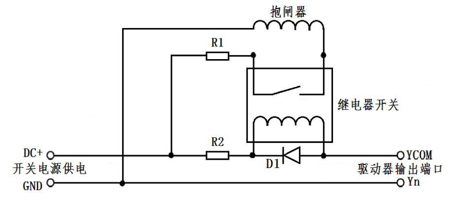
imagethree point six Schematic diagram of brake motor brake pad wiring
tablethree point one three Schematic diagram and parameter description of brake motor and brake pad connection
name | logo | Instructions |
Switching power supply | DC+ | pick up+24or+5Vpower supply |
GND | Grounding terminal | |
Drive output port | YCOM | Single end output port, common end compatible, both positive and negative |
In | One of the output ports needs to be configured as‘Brake control signal’function | |
protective resistor | R1 | If the brake isDC24VPower supply, thenR1Choose to be smaller or not connected; If the brake isDC5VPower supply, thenR1The selection should be larger; |
protective resistor | R2 | R2Can be connected1~2KLimit the current of the resistor to prevent damage to the optocoupler components inside the driver; Please refer to the relay specification sheet to determine whether it needs to be connected; |
freewheeling diode | D1 | Protect the internal components of the driver from being damaged by induced voltage; Please refer to the relay specification sheet to determine whether it needs to be connected; |
Brake Brake | The control mechanism with a brake motor is generally in a released state after the power is connected, and the motor can run freely. Before use, it is necessary to confirm the power supply voltage to avoid burning out the brake due to high voltage; | |
name | Instructions | function | |
Encoder | EB+ | encoder interface | Connect the encoderATheBSignal, pay attention to the line sequence |
EB- | |||
EA+ | |||
EA- | |||
+5V | Encoder power interface | encoder5VPositive end of power supply | |
GND | encoder5VNegative terminal of power supply | ||
name | Instructions | function | |
Motor | A+ | motor interface | Two phase stepper motor wiring port If it is a closed-loop motor, attention should be paid to the wire sequence |
A- | |||
B+ | |||
B- | |||
name | Instructions | function | |
VAC/VDC | AC1/DC+ | power supplyinterface | power input AC20V~50V/DC24V~70V |
AC2/DC- | |||
 Company Profile