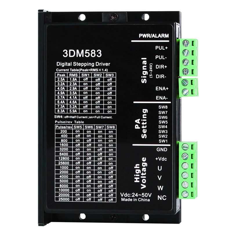
3DM583 is GRMOT launched three-phase Digital stepper driver,Adopting the control principle of class servo,The integration of vector control technology, built-in micro segmentation technology, and adaptive filtering technology greatly optimizes the performance of stepper motors,It runs smoothly at low, medium, and high speeds with low noise.The precise and smooth pure sine current vector control technology effectively reduces motor heating. Its cost-effectiveness is extremely high,canenoughsatisfyceaseMost applications require it.
The normal driving voltage range of 3DM583 driver is DC24~50V, suitable for three-phase hybrid stepper motors with peak current below 8.3A and outer diameter of 42~86mm.
one Electrical specifications
Instructions | 3DM583 | |||
minimum | typical value | maximum | unit | |
output current | two point five | - | eight point three | A |
Input power supply voltage | twofour | thirty-six | fifty | VDC |
Control signal input current | seven | ten | sixteen | mA |
Step pulse frequency | 0 | - | two hundred | KHz |
insulation resistance | fifty |
|
| MΩ |
two Usage environment and parameters
cooling method | natural coolingFan cooling | |
Usage environment | occasion | Cannot be placed next to other heat generating equipment. Avoid dust, oil mist, corrosive gases, high humidity, and strong vibration areas. Combustible gases and conductive dust are prohibited |
temperature | 0——50℃ | |
humidity | 40—90%RH | |
vibration | 10~55Hz/0.15mm | |
storage temperature | -20℃~65℃ | |
one Mechanical installation diagram
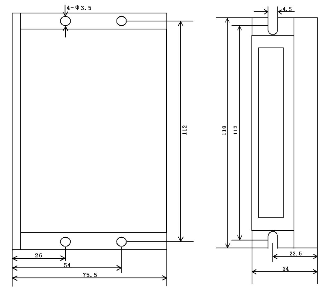
Front installation diagram Side installation diagram
imageInstallation dimension diagram (unit: mm)
※ It is recommended to use side installation for better heat dissipation. When designing the installation size, pay attention to the terminal size and wiring!
one Interface description
1)Control signal interface
name | function |
PUL+ | Pulse control signal:+Both 5V and 24V can be driven, with effective rising edge. Whenever the pulse changes from high to low, the motor takes one micro stepIn order to reliably respond to pulse signals, the pulse width should be greater than2 μs. |
PUL- | |
DIR+ | directioncontrolSignal:+Both 5V and 24V can be driven,tall/Low level signal.To ensure reliable commutation of the motor, the direction signal should be at least prior to the pulse signalEstablish in 5 μ s. The initial running direction of the motor is related to the motor wiring, and swapping any phase winding (such as A+, A - swapping) can change the initial running direction of the motor. |
DIR | |
One + | enablecontrolSignal:+Both 5V and 24V can be driven,tall/Low level signal.Used to enable or prohibitOperation of the motor.whenWhen ENA+is connected to+5V and ENA - is connected to a low level, the driver will cut off the current of each phase of the motor to make it in a free state, and the step pulse will not be responded to at this time. When this function is not needed, the enable signal terminal can be suspended. |
One - |
2)Strong electrical interface
name | function |
GND | DC power supply ground |
+VDC | Positive pole of power supply, range:DCtwofour~50V, Recommended+36V |
U | Connect the motorU-phase output, pay attention to phase sequence |
V | Connect the motorV-phase output, pay attention to phase sequence |
W | Connect the motorW-phase output, pay attention to phase sequence |
NC | Suspended, not connected |
3)status indicator
greenLED is a power indicator light. When the driver is powered on,thatLED is always on; When the driver cuts off the power,thatThe LED is turned off.
redLED is a fault indicator light, which flashes cyclically for 3 seconds when a fault occurs; When the fault is eliminated by the user, the red LED remains off. The flashing frequency of the red LED within 3 seconds represents different fault information, and the specific relationship is shown in the table below:
serial number | Number of flashes | redLEDFlashing waveform | Fault Description |
one | two |
| Overvoltage fault (voltage)>DCfive0V) |
two | three |
| Undervoltage fault(voltage<DC20V) |
three | five |
| Motor open circuit(Missing phase) |
two Control signal interface circuit


image2 Input Interface Circuit
3DM583driveControl signal terminaladoptdifferenceType interface circuit,Applicable differential signalTheSingle ended common cathode and common anode interfaces, built-in high-speed optocoupler, strong anti-interference ability in harsh environments. Schematic diagram of interface circuitAs shown in the figureAs shown in Figure 2.
▶Attention:3DM583for5V-24V universal driver, therefore the signal control terminal does not require a series resistor!
three Control signal timing diagram
To avoid some mistakes and deviations,PULTheDIR and ENA should meet certain requirements, as shown in the following figure:

imagethree Control signal timing diagram
Notes:
1)t1:ENA (Enable Signal) should be determined as high at least 5ms in advance of DIR. Generally, it is recommended to suspend ENA+and ENA -.
2)T2: DIR at least in advancePLSfalling edgeDetermine its state as high or low within 5 μ s.
3)T3: The pulse width should not be less than 2.5 μ s.
4)t4:Low level width not less than2.5μs.
four Wiring requirements
1)To prevent interference with the driver, it is recommended to use shielded cable wires for control signals, and short-circuit the shielding layer to the ground wire. Unless otherwise specified, the shielding wire of the control signal cable should be grounded at one end: the upper computer end of the shielding wire should be grounded, and the driver end of the shielding wire should be suspended. Only grounding at the same point is allowed within the same machine. If it is not a real grounding wire, it may cause serious interference, and the shielding layer should not be connected at this time.
2)Pulse and direction signal lines and motor lines are not allowed to be wrapped side by side, it is best to separate them at leastMore than 10cm, otherwise motor noise can easily interfere with pulse direction signals, causing inaccurate motor positioning, system instability, and other faults.
3)If a power supply supplies multiple drivers, parallel connection should be adopted at the power supply, and chain connection from one driver to another is not allowed.
4)It is strictly prohibited to plug and unplug the strong current terminals of the drive when it is live. When the live motor stops, there is still a large current flowing through the coil,electrifiedPulling and unplugging terminals will cause a huge instantaneous induced electromotive force to burn out the driver.
5)It is strictly prohibited to add tin to the wire head before connecting it to the terminal block, otherwise it may cause overheating and damage to the terminal due to increased contact resistance.
6)The wiring head should not be exposed outside the terminal to prevent accidental short circuit and damage to the driver.
4DIP switchfunctionsetting
3DM583The driver adoptseightDIP switch,SW1-SW3 is used to set the current; SW4 selects full flow or half flow lock machine; SW5-SW8 are used for subdivision settings.The detailed description is as follows:
SW1 | SW2 | SW3 | SW4 | SW5 | SW6 | SW7 | SW8 |
CURRENT SETTING | Half current | Subdivision Settings | |||||
one CURRENT SETTING
outputeffectivecurrent(A) | SW1 | SW2 | SW3 | |
two point five | one point eight | off | off | off |
three point two | two point three | on | off | off |
four | two point nine | off | on | off |
four point nine | three point five | on | on | off |
five point seven | four point one | off | off | on |
six point four | four point six | on | off | on |
seven point three | five point two | off | on | on |
eight point three | five point nine | on | on | on |
two Static current setting
Static current availableSW4 dip switch setting,offSet the static current to half of the dynamic current,onIndicates that the static current is the same as the dynamic current. averageIn useShouldSW4 is set to off to reduce the heat generation of the motor and driver,improveReliability. pulseinputAfter stopping,The current automatically decreases to half.
three segmentSettings
step count/Transform | SW5 | SW6 | SW7 | SW8 |
two hundred | on | on | on | on |
four hundred | off | on | on | on |
eight hundred | on | off | on | on |
one thousand and six hundred | off | off | on | on |
three thousand and two hundred | on | on | off | on |
six thousand and four hundred | off | on | off | on |
twelve thousand and eight hundred | on | off | off | on |
twenty-five thousand and six hundred | off | off | off | on |
one thousand | on | on | on | off |
two thousand | off | on | on | off |
four thousand | on | off | on | off |
five thousand | off | off | on | off |
eight thousand | on | on | off | off |
ten thousand | off | on | off | off |
twenty thousand | on | off | off | off |
twenty-five thousand | off | off | off | off |
5Power supply selection
The power supply voltage is within the specified rangeinsideThey can all work normally,3DM583It is best to use a voltage regulator for the driverdirect currentSwitching power supply, attention should be paid to setting the output current range of the switching power supply to the maximum.It can also be usedNon regulated DC power supply, but attention should be paid to rectifying itofThe peak value of voltage ripple shall not exceed its specified maximum voltage. It is recommended that users use a DC voltage lower than the maximum voltage for power supply to avoid grid fluctuations exceeding the operating range of the driver voltage.
▶Note:
1)When wiring, be careful not to reverse the polarity of the power supply;
2)Pay attention to the power supply when wiringThe position of the interface should not be connected to the motor port. It is best to confirm again whether it is connected correctly after connection;
3)It is best to use a stabilized DC voltageswitchpower supplypower supply;
4)Adopting non voltage regulationType DCWhen powered on, the output capacity of the power supply current should be greater than the set current of the driver60% is sufficient;
5)Adopting voltage stabilizationType DCWhen switching on or off the power supply, the output current of the power supply should be greater than or equal to the operating current of the driver;
6)To reduce costs, two or three drivers can share a power supply, but it should be ensured that the power supply is sufficiently large.
VIprotection function
When the input voltage is higher thanDC50V time,Driver red lightflickerTwice, andwith3 secondsFor the cyclerepeatedlyflickerAt this time, it is necessary to arrangeexceptFault,againPower on reset.
VacbelowDC20V time,Driver red lightflickerthreeSecondly, andwith3 secondsFor the cyclerepeatedlyflickerAt this time, it is necessary to arrangeexceptFault,againPower on reset.
whenAt the beginning of power on, the motor is out of phaseWhen the driver is redflickerfiveSecondly, andwith3 secondsFor the cyclerepeatedlyflickerAt this moment,Must be arrangedexceptFault,againPower on reset.
 Company Profile