
HS86 is GRMOT newly launched Equipped with serial port debugging functiondigitalmixstepservoDrive, using the latest technology32-bit DSPcontrolTechnology,integratedMODBUS-RTU standard protocol specification,userSoftware can be debugged through the upper computerSettings200-four thousandAny subdivision within 0 andMultiple parameters such as working mode,Greatly enriching the practical functions of the product,canenoughMeet the application needs of most occasions.
The HS86 driver adopts a servo like control principle,It is compatible with the dual advantages of open-loop stepper and servo systems, completely solving the problem of step loss in open-loop stepper, greatly improving the performance of the stepper system, while reducing motor heating and low-speed vibration. Compared to servo systems, it greatly reduces the difficulty of debugging, has the advantages of fast start stop and vibration free shutdown, and is small in size, low in cost, and high in cost-effectiveness, which can meet the needs of the vast majority of applications.
Electrical, mechanical, and environmental indicators
one Electrical specifications
Instructions | HS86 | |||
minimum | typical value | maximum | unit | |
Input power supply voltage | twenty | sixty | eighty | VAC |
Control signal input current | seven | ten | sixteen | mA |
Step pulse frequency | 0 | - | two hundred | KHz |
insulation resistance | fifty |
|
| MΩ |
two Usage environment and parameters
cooling method | natural coolingFan cooling | |
Usage environment | occasion | Cannot be placed next to other heat generating equipment. Avoid dust, oil mist, corrosive gases, high humidity, and strong vibration areas. Combustible gases and conductive dust are prohibited |
temperature | 0——50℃ | |
humidity | 40—90%RH | |
vibration | 10~55Hz/0.15mm | |
storage temperature | -20℃~65℃ | |
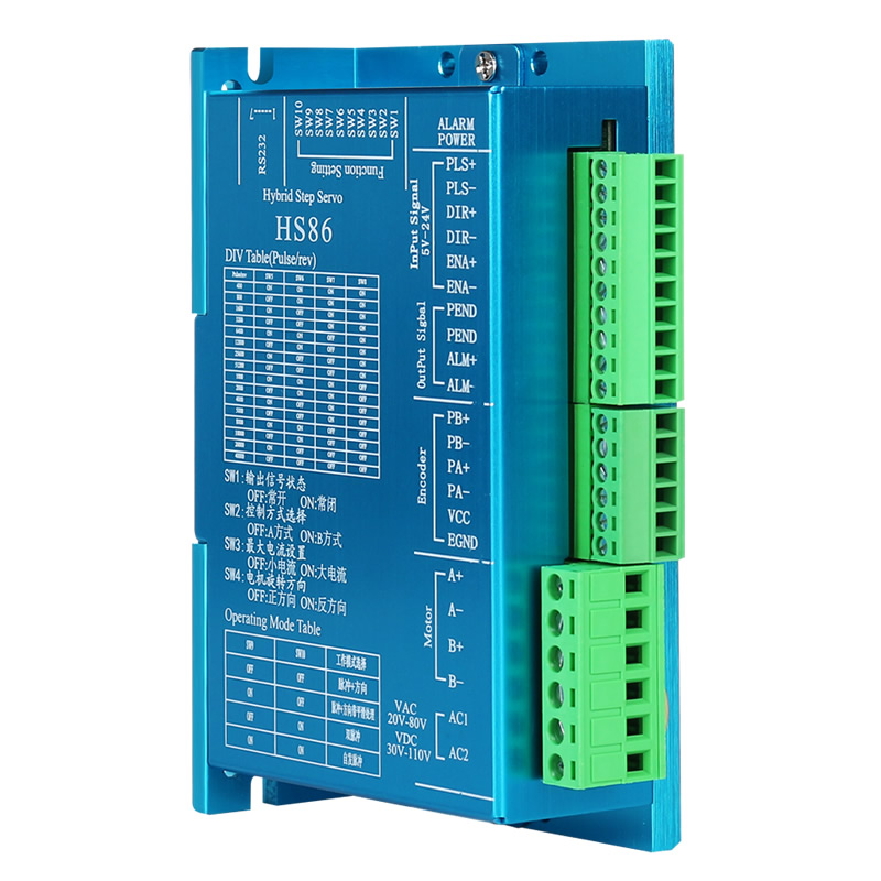
one Interface description
1)Control signal interface
name | function |
PLS+ | Pulse control signal:+Both 5V and 24V can be driven, with effective rising edge. Whenever the pulse changes from high to low, the motor takes one micro stepIn order to reliably respond to pulse signals, the pulse width should be greater than2 μs. |
PLS- | |
DIR+ | directioncontrolSignal:+Both 5V and 24V can be driven,tall/Low level signal.To ensure reliable commutation of the motor, the direction signal should be at least prior to the pulse signalEstablish in 5 μ s. The initial running direction of the motor is related to the motor wiring, and swapping any phase winding (such as A+, A - swapping) can change the initial running direction of the motor. |
DIR | |
One + | enablecontrolSignal:+Both 5V and 24V can be driven,tall/Low level signal.Used to enable or prohibitOperation of the motor.whenWhen ENA+is connected to+5V and ENA - is connected to a low level, the driver will cut off the current of each phase of the motor to make it in a free state, and the step pulse will not be responded to at this time. When this function is not needed, the enable signal terminal can be suspended.Besides,The ENA terminal can also be used to clear the out of tolerance alarm signal. |
One - |
2)output signalinterface
name | function |
PEND+ | In place signal output: When the motor reaches the position specified by the control command, the in place signal output is valid; PEND+is connected to the positive terminal of the output power supply through a pull-up resistor, and PEND - is connected to the signal input terminal of the controller; The maximum driving current is 50mA. |
PEND- | |
ALM+ | Alarm signal output: When overcurrent, overvoltage, undervoltage or position deviation alarm occurs, the alarm signal output is valid; ALM+Connect a pull-up resistor to the positive pole of the output power supply, ALM - Connect to the signal input terminal of the controller; The maximum driving current is 50mA. |
ALM- |
3)encoder interface
name | function |
PB+ | encoderB-phase input interface, pay attention to the line sequence. |
PB- | |
PA+ | encoderAttention should be paid to the line sequence of the A-phase input interface. |
PA- | |
VCC | encoderPositive terminal of 5V power supply. |
EGND | encoder5V power supply negative terminal. |
▶AttentionThe wiring sequence of the encoder is marked on the bottom label of the closed-loop motor, and must be strictly followed according to the wiring on the label.
4)Strong electrical interface
name | function |
AC1 | AC input power supply,AC20V-80V(DC30V-110V) |
AC2 | |
A+、A- | motorA-phase coilPay attention to the line sequence. |
B+、B- | motorB-phase coilPay attention to the line sequence. |
▶AttentionThe bottom label of the closed-loop motor indicates the wiring sequence of the motor, which must be strictly followed according to the wiring on the label.
5)232 communication interface
The serial communication interface of HS86 driver adopts PH2.0-7P terminals,Can be connected through a dedicated serial port cableLine by LineUSB to TTL serial port conversion toolconnect toPC, do not plug or unplug with power on!by means ofPCEnd, customercanSettingsrequiredparameters,For details such as current, subdivision, and working mode, please refer to the upper computer software interface.
terminal number | symbol | name | Instructions |
one | NC | - | For internal use only |
two | NC | - | For internal use only |
three | GND | RS232 communication ground | 0V |
four | NC | - | For internal use only |
five | NC | - | For internal use only |
six | TXD | RS232 sender |
|
seven | RXD | RS232receiveend |
|
▶Note:HS86andPC machineevenThe connected cable must be a dedicated cable (randomly included depending on the user's situation) and confirmed before use to avoid damage.
6)status indicator
greenLED is a power indicator light. When the driver is powered on,thatLED is always on; When the driver cuts off the power,thatThe LED is turned off.
redLED is a fault indicator light, which flashes cyclically for 3 seconds when a fault occurs; When the fault is eliminated by the user, the red LED remains off. The flashing frequency of the red LED within 3 seconds represents different fault information, and the specific relationship is shown in the following table:
serial number | Number of flashes | redLEDFlashing waveform | Fault Description |
one | one |
| overcurrentThephase-to-phase short circuitOr poor contactfault |
two | two |
| Overvoltage fault (voltage)>AC80V/DC110V) |
three | three |
| Undervoltage fault(voltage<AC20V/DC30V) |
four | five |
| Motor open circuit(Missing phase) |
▶Note:When the deviation alarm is triggered, it will be redThe LED is constantly on,If the over tolerance alarm is caused by overvoltage or undervoltage, it will be redThe LED will flash rapidly without interruption. Besides,When an out of tolerance alarm occurs, it can be triggered throughEnable the ENA end to clear the out of tolerance alarm signal.
two Control signal interface circuit
HS86driveControl signal terminaladoptdifferenceType interface circuit,Applicable differential signalTheSingle ended common cathode and common anode interfaces, built-in high-speed optocoupler, strong anti-interference ability in harsh environments. Schematic diagram of interface circuitAs shown in the figureAs shown in Figure 2.


image2 Input Interface Circuit
▶Attention:HS86for5V-24V universal driver, therefore the signal control terminal does not require a series resistor!
three Control signal timing diagram
To avoid some mistakes and deviations,PLSTheDIR and ENA should meet certain requirements, as shown in the following figure:

imagethree Control signal timing diagram
Notes:
1)t1:ENA (Enable Signal) should be determined as high at least 5ms in advance of DIR. Generally, it is recommended to suspend ENA+and ENA -.
2)T2: DIR at least P in advanceLSfalling edgeDetermine its state as high or low within 5 μ s.
3)T3: The pulse width should not be less than 2.5 μ s.
4)t4:Low level width not less than2.5μs.
four Control signal mode setting
Pulse trigger edge selection: throughPC softwarecanSet the pulse rising edge or falling edge trigger to be effective.
five Wiring requirements
1)To prevent interference with the driver, it is recommended to use shielded cable wires for control signals, and short-circuit the shielding layer to the ground wire. Unless otherwise specified, the shielding wire of the control signal cable should be grounded at one end: the upper computer end of the shielding wire should be grounded, and the driver end of the shielding wire should be suspended. Only grounding at the same point is allowed within the same machine. If it is not a real grounding wire, it may cause serious interference, and the shielding layer should not be connected at this time.
2)Pulse and direction signal lines and motor lines are not allowed to be wrapped side by side, it is best to separate them at leastMore than 10cm, otherwise motor noise can easily interfere with pulse direction signals, causing inaccurate motor positioning, system instability, and other faults.
3)If a power supply supplies multiple drivers, parallel connection should be adopted at the power supply, and chain connection from one driver to another is not allowed.
4)It is strictly prohibited to plug and unplug the strong current terminals of the drive when it is live. When the live motor stops, there is still a large current flowing through the coil,electrifiedPulling and unplugging terminals will cause a huge instantaneous induced electromotive force to burn out the driver.
5)It is strictly prohibited to add tin to the wire head before connecting it to the terminal block, otherwise it may cause overheating and damage to the terminal due to increased contact resistance.
6)The wiring head should not be exposed outside the terminal to prevent accidental short circuit and damage to the driver.
4DIP switchfunctionsetting
HS86The driver adoptstenDIP switch,SW1-SW4 is used for ALM and PEND output configuration settings, algorithm selection, maximum peak current setting, and direction selection; SW5-SW8 are used for subdivision settings; SW9-SW10 is used for working mode selection.The detailed description is as follows:
SW1 | SW2 | SW3 | SW4 | SW5 | SW6 | SW7 | SW8 | SW9 | SW10 |
Function Settings | Subdivision Settings | Work Mode | |||||||
one Function Settings
1)ALMThePENDOutput configuration settings
Set the output signal resistance state of ALM and PEND to SW1. When SW1=off, it is in a normally open state; When SW1=on, it is in a normally closed state.
2)algorithm selection
SW2 is used to select the control algorithm for the driver, and when SW2=off, it is algorithm A; When SW2=on, it is the B algorithm.
3)Maximum current setting
Set the maximum output current of the driver to SW3. When SW3=off, it is a small current output, mainly suitable for 57 or 60 closed-loop motors; When SW3=on, it is a high current output, mainly suitable for 86 closed-loop motors.
4)Direction selection
SW4 sets the initial rotation direction of the motor, and when SW4=off, it rotates in the positive direction; When SW4=on, it rotates in the opposite direction.
two segmentSettings
step count/Transform | SW5 | SW6 | SW7 | SW8 | Subdivision Explanation |
four hundred | on | on | on | on | whenSW5、SW6、SW7、SW8都为Off statusAt that time, the usercanpassPC softwareSettingsAny value between 200-40000segmentvalueThe resolution is1. |
eight hundred | off | on | on | on | |
one thousand and six hundred | on | off | on | on | |
three thousand and two hundred | off | off | on | on | |
six thousand and four hundred | on | on | off | on | |
twelve thousand and eight hundred | off | on | off | on | |
twenty-five thousand and six hundred | on | off | off | on | |
fifty-one thousand and two hundred | off | off | off | on | |
one thousand | on | on | on | off | |
two thousand | off | on | on | off | |
four thousand | on | off | on | off | |
five thousand | off | off | on | off | |
eight thousand | on | on | off | off | |
ten thousand | off | on | off | off | |
twenty thousand | on | off | off | off | |
forty thousand | off | off | off | off |
three Work Mode
SW9 | SW10 | Work mode selection | Remarks |
off | off | pulse+Direction | whenWhen SW9 and SW10 are both in the off state, users can use PC software toSet the working mode by yourself. |
on | off | pulse+Smooth processing of directional bands | |
off | on | double pulse | |
on | on | Spontaneous pulse |
▶Note:The modification needs to be powered on again to take effect.
5Power supply selection
The power supply voltage is within the specified rangeinsideThey can all work normally,HS86driveTransformer power supply can be used, and it is recommended to use the AC output voltage of the transformerNot exceeding its specified maximum voltage.HS86drivecan alsoPowered by a non regulated DC power supply,However, it should be noted that after rectificationofThe peak value of voltage ripple shall not exceed its specified maximum voltage.Recommend users to use a DC voltage lower than the maximum voltage for power supplyTo avoid grid fluctuations exceeding the operating voltage range of the driver.
If using a regulated switching power supply for power supply, attention should be paid to setting the output current range of the switching power supply to the maximum.
▶Note:
1)Pay attention to the power supply when wiringThe position of the interface should not be connected to the motor port. It is best to confirm again whether it is connected correctly after connection;
2)It is best to use a non regulated power supply;
3)Adopting non voltage regulationtypeWhen powered on, the output capacity of the power supply current should be greater than the set current of the driver60% is sufficient;
4)Adopting voltage stabilizationtypeWhen switching on or off the power supply, the output current of the power supply should be greater than or equal to the operating current of the driver;
5)To reduce costs, two or three drivers can share a power supply, but it should be ensured that the power supply is sufficiently large.
VIprotection function
one short circuit protection
When a phase to phase short circuit occursTheWhen there is an overcurrent inside the drive, the red light of the drive will turn redflickerOnce, andwith3 secondsFor the cyclerepeatedlyflickerAt this moment,Must be arrangedexceptFault,againPower on reset.
When the input voltage is higher thanAC80Vtime,Driver red lightflickerTwice, andwith3 secondsFor the cyclerepeatedlyflickerAt this moment,Must be arrangedexceptFault,againPower on reset.
VacbelowAC20Vtime,Driver red lightflickerthreeSecondly, andwith3 secondsFor the cyclerepeatedlyflickerAt this moment,Must be arrangedexceptFault,againPower on reset.
whenAt the beginning of power on, the motor is out of phaseWhen the driver is redflickerfiveSecondly, andwith3 secondsFor the cyclerepeatedlyflickerAt this moment,Must be arrangedexceptFault,againPower on reset.
When an out of tolerance alarm occurs, the red light of the driver will remain constantly on or flash rapidly.at this moment, can be done throughClear the alarm on the ENA end or power on and reset again.
Adapted motor
| GR57HS56-3M | GR57HS80-3M | GR57HS80-30-3M | |
| GR60HS86-3M | GR60HS86-30-3M | ||
| GR86HS80-3M | GR86HS118-38 | GRHS86156-3M |
 Company Profile